Powering HDMI to VGA adapters for Mac Mini
Mac for DataCenter
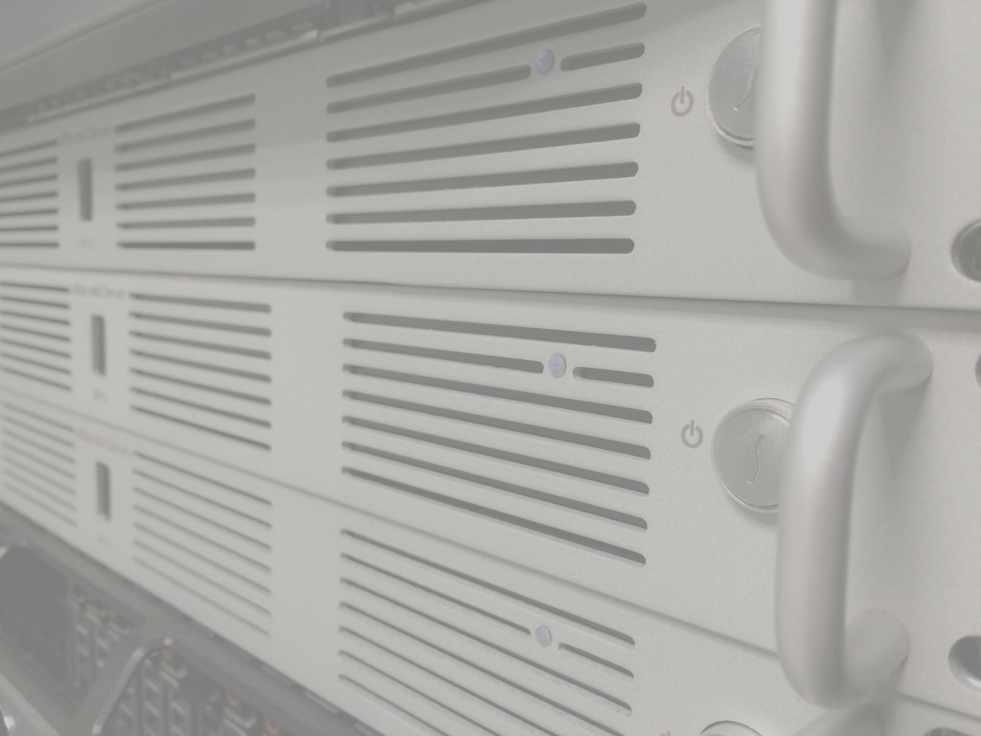
Apple Mac Pro’s are great machines with quality and powerful hardware. And it fits nice and looks unique on a desktop. But what when you still have some applications that need to run on Mac server ? There comes the problem, Mac Pro’s are difficult, voir impossible to rack in a DataCenter. They are not made for that. The solution, adopted by many people is to turn to Mac Mini’s. These mini machines are small and fit well in DataCenter racks. Some companies even do business with it, they build enclosures designed to house Mac Mini machines in a rack.
VGA console problem
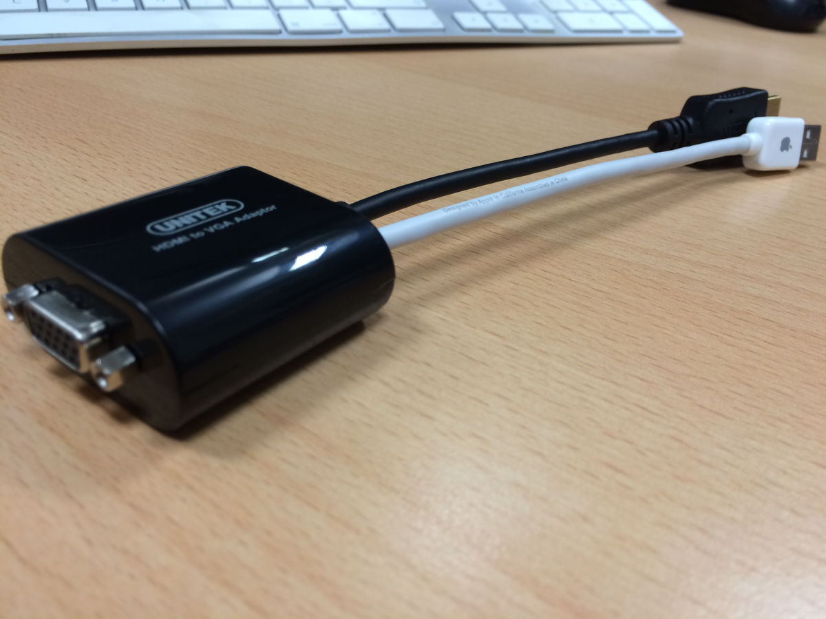
Rack enclosures for Mac Mini’s are nice. We installed few of them. They look nice. The only problem was that the HDMI to VGA adapters for rack console were not working. As it turns out these adapters have active electronic components that need power. And apparently Mac Mini’s HDMI port is not suplying the required power or supplied power is not sufficient.
There is a discussion in Apple Support Communities forums on the subject:
The quick fix here would be to abandon HDMI-VGA adapter and to use instead Apple’s mini-display (Thunderbolt) port with corresponding adapter to get the required VGA signal. Helas, our Mac Mini’s have a single Thunderbolt port and it is already used for 10 GbE networking.
The other solution was to try to power the adapter electronics from USB port. This is the way I explored and it worked.
Powering HDMI-VGA adapter from USB
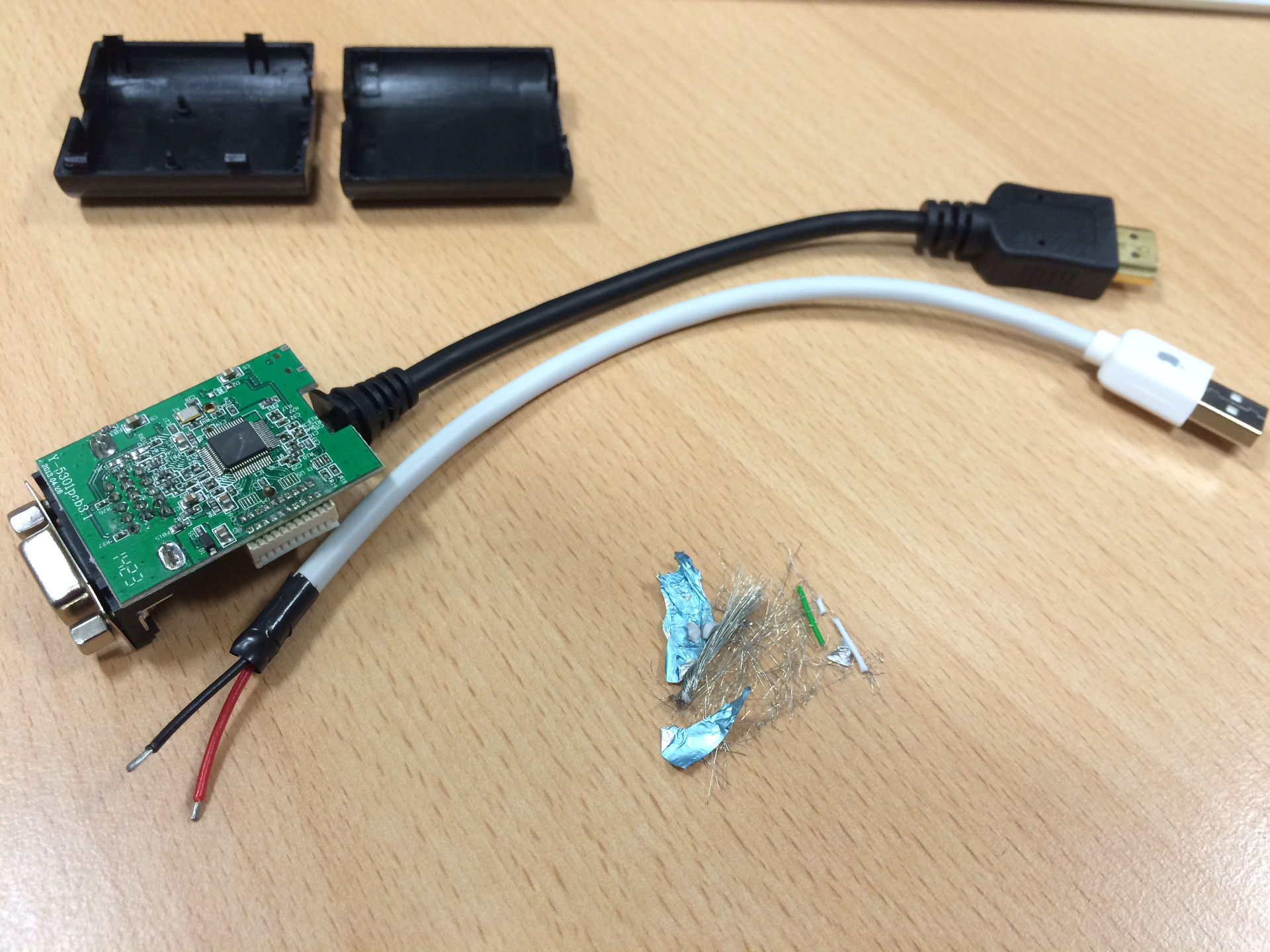
USB cable
I had to find a cable with USB plug that I could sacrifice, after cutting it on required length I checked USB pin-out and then used multimeter to locate which lines map to the power pins. The colors of the lines confirmed that Ground (GND) is flowing on the black line and and +5 Volt (5VDC) on the red one. Good, that’s what we need for power.
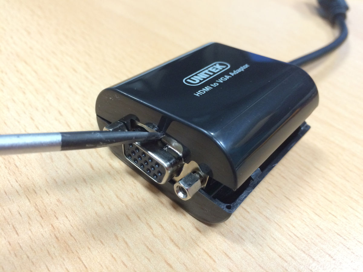
Using the screwdriver I removed adapter cover, then cut the USB cable, cleaned it and prepared power lines with soldering iron. The unused USB data lines were cut in different length and isolated with tape from the rest.
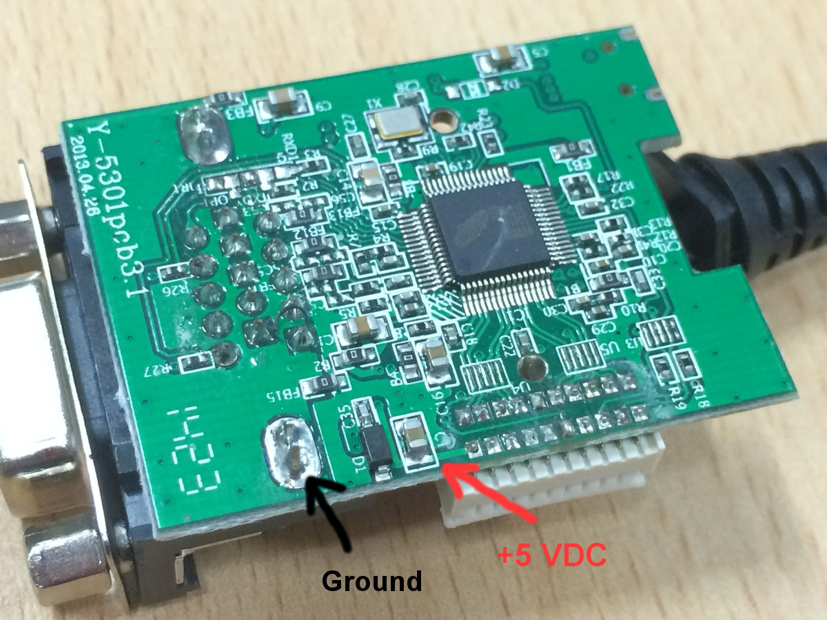
Electronics board
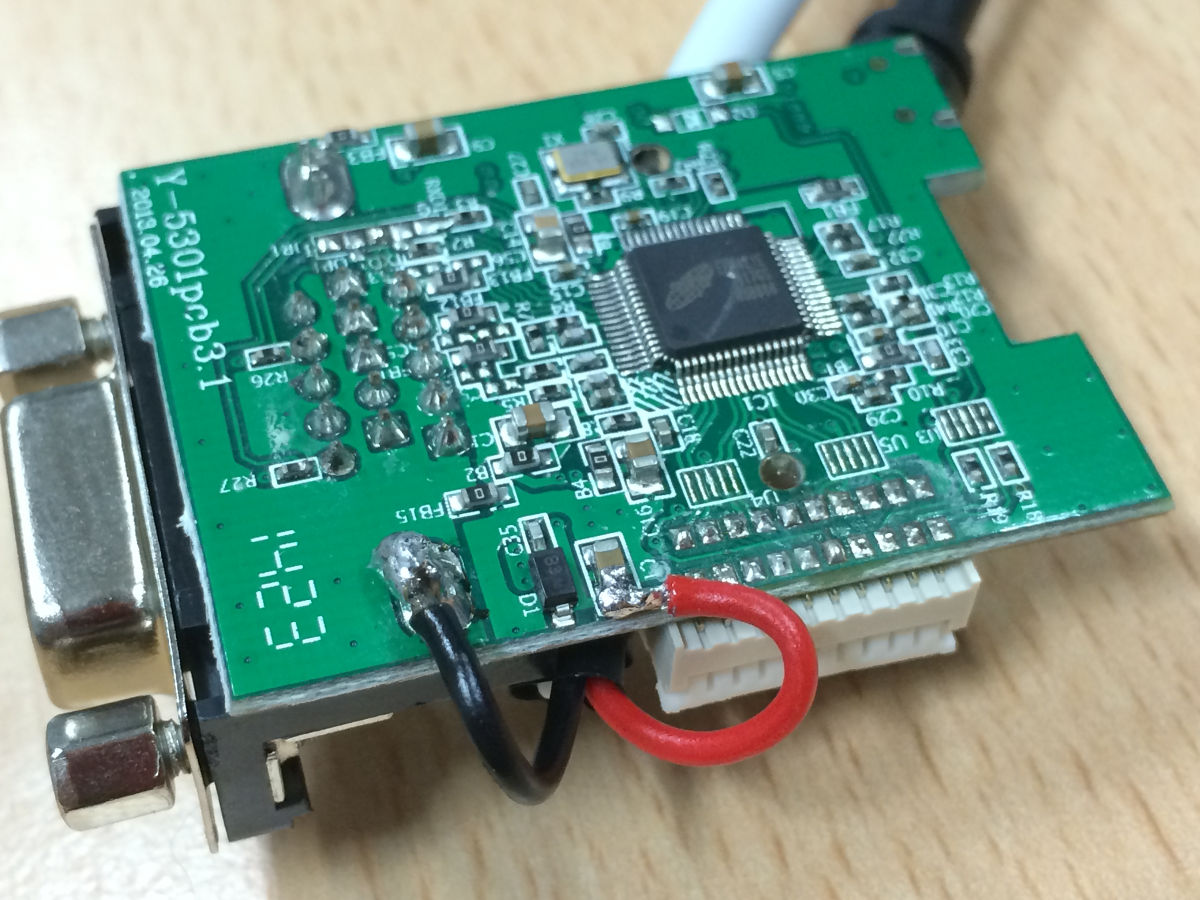
Now the delicate part. On the adapter electronics board I had to identify where are the power contacts. Here again, HDMI pin-out schematics helped me to select the right pins on the plug and then multimeter showed me on the board which contacts circulate the power. Now it was just the matter of connecting USB power lines to the board with soldering iron.
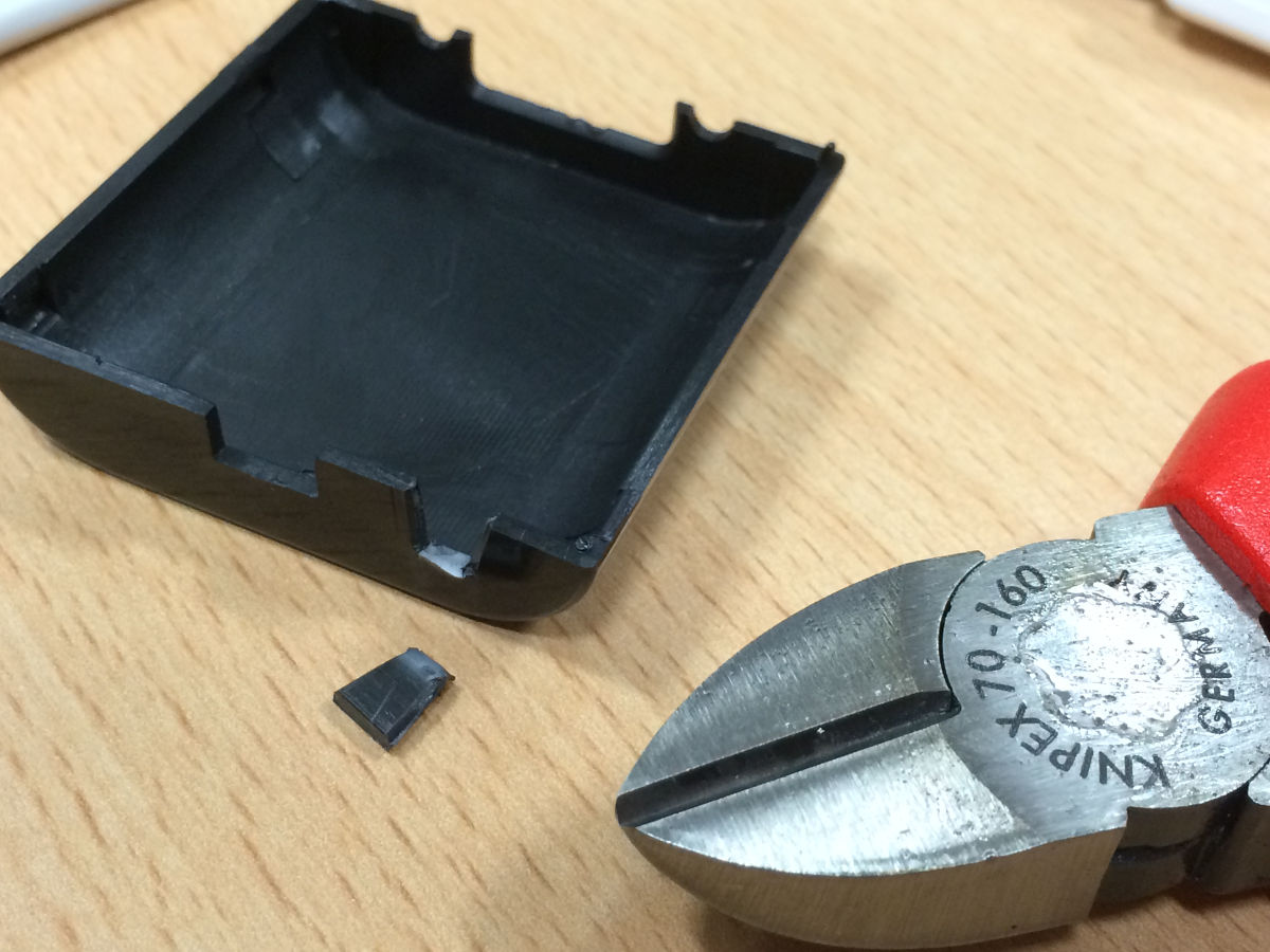
Finishing touch
Last thing to do was to cut the adapter’s cover to make a small hole approximately the same diameter as USB cable. Put the cover back to close adapter casing, all done.